Difference between revisions of "Modding"
From veswiki
| Line 1: | Line 1: | ||
<H1>Composite video modification</H1> | <H1>Composite video modification</H1> | ||
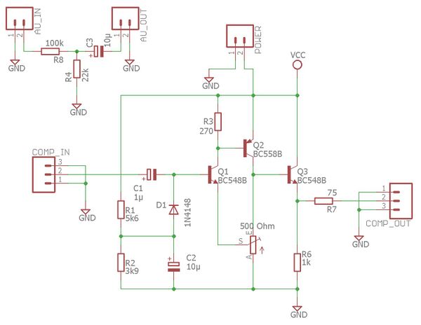
<H2>Working mod schematic</H2> | <H2>Working mod schematic</H2> | ||
| − | [[File:Channel F composite mod schematic.jpg| | + | [[File:Channel F composite mod schematic.jpg|600px]]<br> |
<br> | <br> | ||
<H2>Example PCB</H2> | <H2>Example PCB</H2> | ||
| − | [[File:Composite mod rendered PCB top.png| | + | [[File:Composite mod rendered PCB top.png|400px]][[File:Composite mod rendered PCB bottom.png|400px]]<br> |
Example of PCB using SMD components. | Example of PCB using SMD components. | ||
<br> | <br> | ||
Revision as of 20:37, 24 April 2019
Composite video modification
Working mod schematic
Example PCB
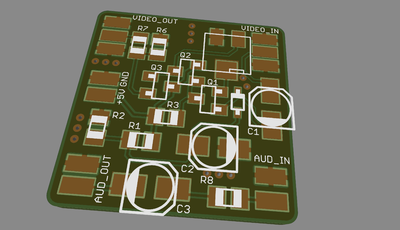

Example of PCB using SMD components.
Hookup
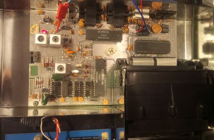
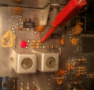
Available 5V shown with red and blue wires in top right position and composite signal source taken with a red clamp on a resistor by the LED.
