Difference between revisions of "Modding"
| Line 8: | Line 8: | ||
<H2>Example PCB:s</H2> | <H2>Example PCB:s</H2> | ||
[[File:Composite mod rendered PCB top.png|400px]][[File:Composite mod rendered PCB bottom.png|400px]]<br> | [[File:Composite mod rendered PCB top.png|400px]][[File:Composite mod rendered PCB bottom.png|400px]]<br> | ||
| − | [[File:THM mod top.png|300px]][[File:THM mod bot.png| | + | [[File:THM mod top.png|300px]][[File:THM mod bot.png|300px]]<br> |
<br> | <br> | ||
Example of PCB:s for either SMD or THM components. <br> | Example of PCB:s for either SMD or THM components. <br> | ||
If you want to have your own PCB made here are Gerber-files for the through hole mount version seen above:<br> | If you want to have your own PCB made here are Gerber-files for the through hole mount version seen above:<br> | ||
[[:File:Channel_F_composite_mod_Gerber_files.zip|Composite mod EagleCAD and Gerber-files (.zip 139kB)]] | [[:File:Channel_F_composite_mod_Gerber_files.zip|Composite mod EagleCAD and Gerber-files (.zip 139kB)]] | ||
| + | <pre> | ||
| + | BOM | ||
| + | C1 1µ E2,5-6 Polarized capacitor | ||
| + | C2 10µ E2,5-6 | ||
| + | C3 10µ E2,5-6 | ||
| + | D1 1N4148 DO35-10 Diode | ||
| + | POT 500 Ohm TRIM_EU-S64Y | ||
| + | Q1 BC548B TO92-EBC NPN Transistor | ||
| + | Q2 BC558B TO92-EBC PNP | ||
| + | Q3 BC548B TO92-EBC NPN | ||
| + | R1 5k6 0207/10 Resistor | ||
| + | R2 3k9 0207/10 | ||
| + | R3 270 0207/10 | ||
| + | R4 22k 0207/10 | ||
| + | R6 1k 0207/10 | ||
| + | R7 75 0207/10 | ||
| + | R8 100k 0207/10 | ||
| + | |||
| + | 0.1 inch spaced/style header connection can be used | ||
| + | </pre> | ||
<br> | <br> | ||
Latest revision as of 21:50, 22 March 2023
Contents
System Fairchild composite video modification
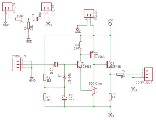
Working mod schematic
Construction can be used for many other machines as well.
Example PCB:s
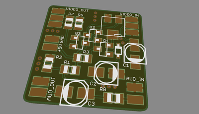
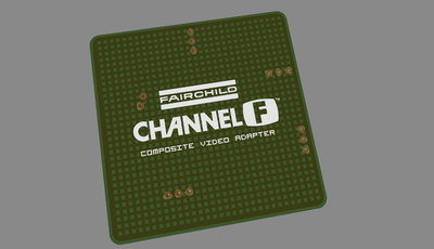
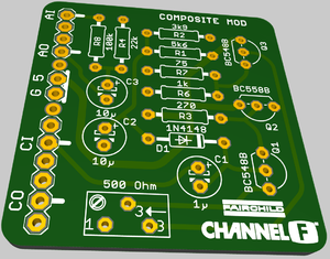
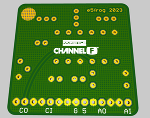
Example of PCB:s for either SMD or THM components.
If you want to have your own PCB made here are Gerber-files for the through hole mount version seen above:
Composite mod EagleCAD and Gerber-files (.zip 139kB)
BOM
C1       1µ            E2,5-6   Polarized capacitor
C2       10µ           E2,5-6
C3       10µ           E2,5-6
D1       1N4148        DO35-10  Diode
POT      500 Ohm       TRIM_EU-S64Y
Q1       BC548B        TO92-EBC NPN Transistor
Q2       BC558B        TO92-EBC PNP
Q3       BC548B        TO92-EBC NPN
R1       5k6           0207/10  Resistor
R2       3k9           0207/10
R3       270           0207/10
R4       22k           0207/10
R6       1k            0207/10
R7       75            0207/10
R8       100k          0207/10

0.1 inch spaced/style header connection can be used
Hookup
Fairchild Video Entertainment System / Channel F
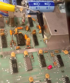
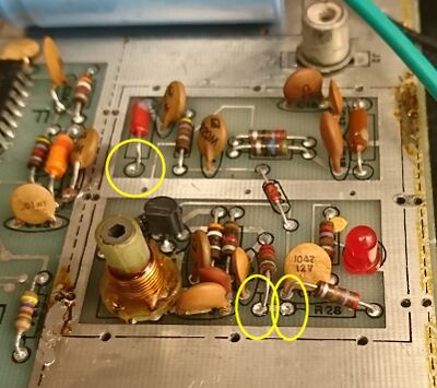
Connect composite signal to the resistor by the RF box where the black clamp is placed.
Audio can be picked directly from speaker output using about 150kOhm in series.
To improve image quality you can desolder RF shield and remove (or just lift one leg) L2 coil and resistors R28, R25
This will disconnect 5V from RF circuit and also disconnect it from the composite signal
Use GND and +5V connecting from the electrolytic cap on the 5V regulator output
Channel F II
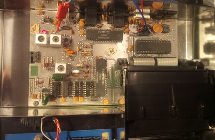
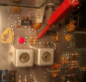
5V can be picked directly from the capacitor, here connected with red and blue wires in top right position of the circuitboard.
One of the locations for composite signal source has been hooked up with a red clamp on a resistor by the LED.
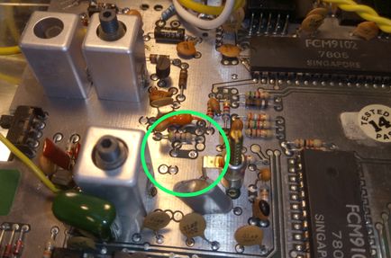
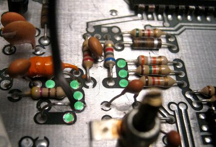
You can lift the jumper in the green circle to improve video quality.
Optional composite video hookup points are located there, marked with green dots.
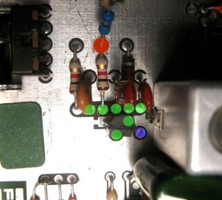
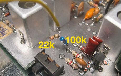
Audio hookup is found right of the channel switch. Connect a 22kOhm and 100kOhm as a voltage divider from GND ro red dot.
This will give an audio volume close to the one via the RF-signal.
Green dots have a low level audio signal, if used instead you may get interference if skipping an inline resistor (R8 in schematic).
SABA Videoplay 2
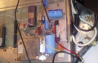
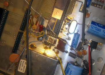
In this example 5V and ground is hooked up directly to the 5V regulator, composite signal is taken from capacitor pin (yellow wire).
The white wire from the speaker is originally connected to the little RF board, connect it to the PCB instead.
In the image you see audio hooked up with a loose resistor and capacitor instead of using the PCB.